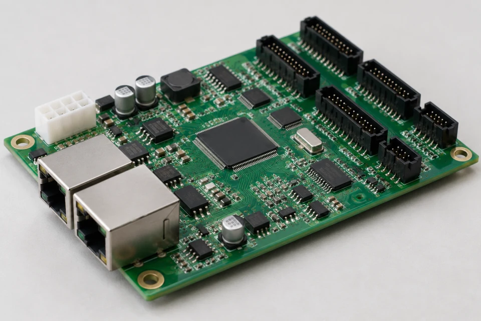
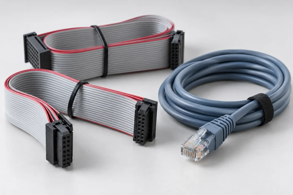
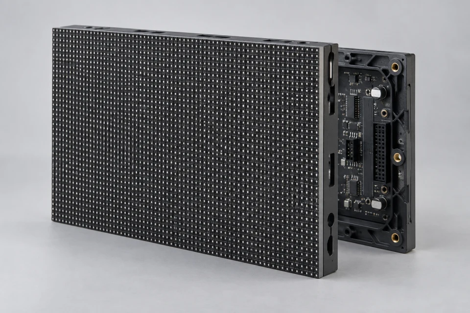
LED HUB Adapter Board Checklist (PDF)
Compare receiver socket, module-output layout, pin map and ribbon orientation before selecting a HUB adapter board.
Download Checklist (PDF)
The HUB board organizes module data connections. Its pinout and receiving-card interface must be verified, even when the connectors appear identical.
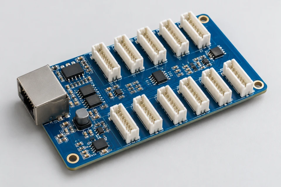
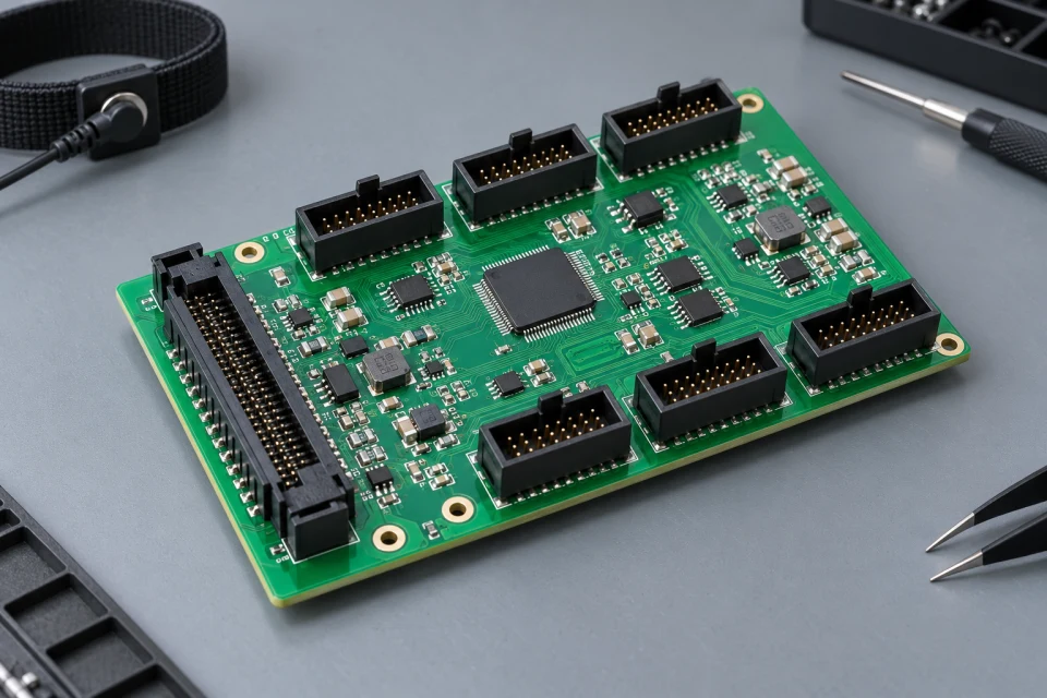
Application: Cabinet assembly, receiver-card integration and interface repair.
Interface to check: Compare receiver-card socket, connector count, HUB pin map and ribbon-cable orientation.
Service note: Mark the cable direction and keep a connector photo with the service record.
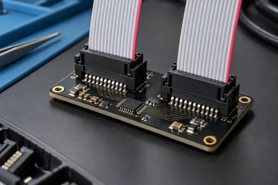
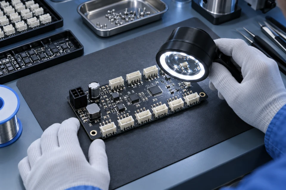
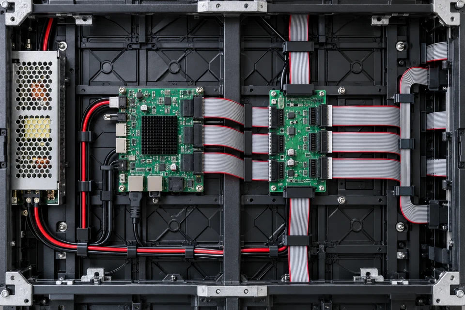
A HUB adapter board routes receiver outputs to the module positions specified in the cabinet wiring diagram. The connector footprint and printed pin map should both be checked during OEM/ODM integration.
A visually similar board can carry a different scan or signal assignment. Providing the original board markings and a clear wiring photograph makes a compatibility review more reliable.
A board distributes the receiver output to the module positions in a cabinet.
Similar-looking boards can carry different signal assignments.
Clear cable routing helps reduce reconnection errors after maintenance.
Compare receiver socket, module-output layout, pin map and ribbon orientation before selecting a HUB adapter board.
Download Checklist (PDF)| Receiver interface | Match the card socket and board format |
|---|---|
| Module outputs | Confirm connector number and arrangement |
| Pin mapping | Compare against the original wiring diagram |
| Ribbon direction | Record keying and cable orientation |
Compare the HUB pin map and connector orientation with the receiver and modules; physically similar boards can wire signals differently.
COMPONENT INQUIRY
Provide photographs of both sides of the HUB board, its connector layout and the receiver model. The pin map is essential when comparing an adapter for service or assembly.