
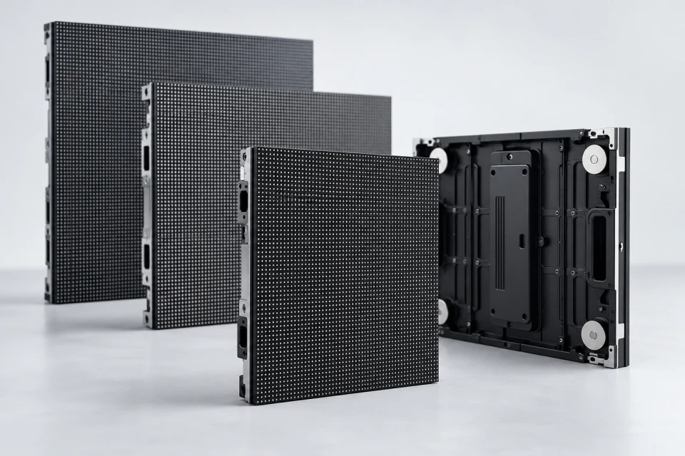
LED Display Modules
Panels for display faces where pitch, mechanical opening and scan configuration must be reviewed together.
Explore Category
Browse the components that define the image, transmit data, deliver power and hold an LED screen together.

Part names are only the start. Confirm pixel pitch, module dimensions, signal mapping, voltage and cabinet fit against the assembly you are building or repairing. Each product page lists the questions that matter before selection.
Move from the display face through control, power and enclosure hardware. Category pages help narrow the selection before you review a specific component.
Panels for display faces where pitch, mechanical opening and scan configuration must be reviewed together.
Explore Category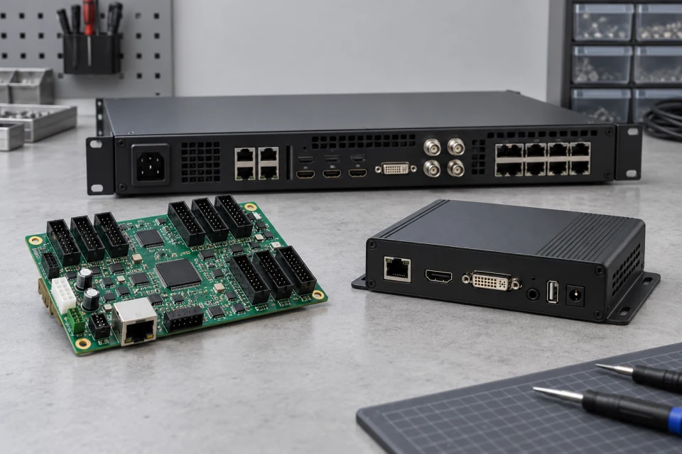
Hardware that receives, processes and distributes a mapped video canvas through compatible cabinets.
Explore Category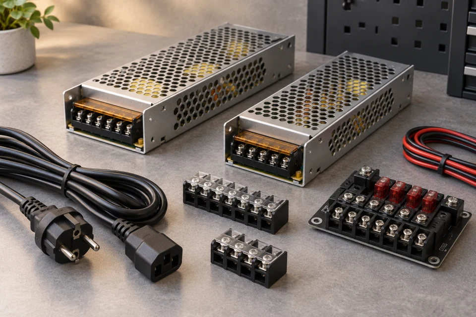
DC conversion and connection parts reviewed as a complete cabinet power route.
Explore Category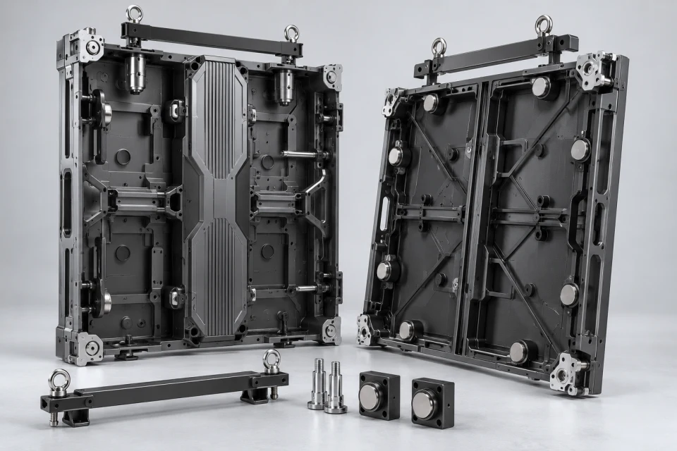
Enclosures that align modules, protect electronics and provide the intended service direction.
Explore Category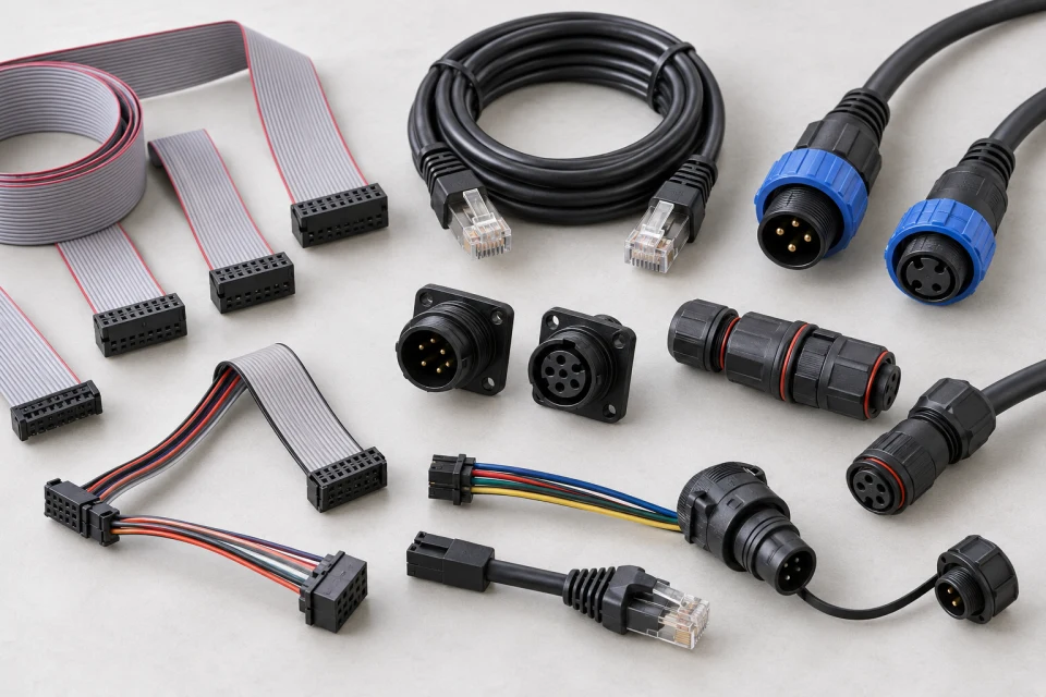
HUB boards and cables that carry data from receiver outputs to module rows.
Explore CategoryThe catalog covers nine commonly specified parts. Send a drawing, model label or bill of materials when an exact match is required.
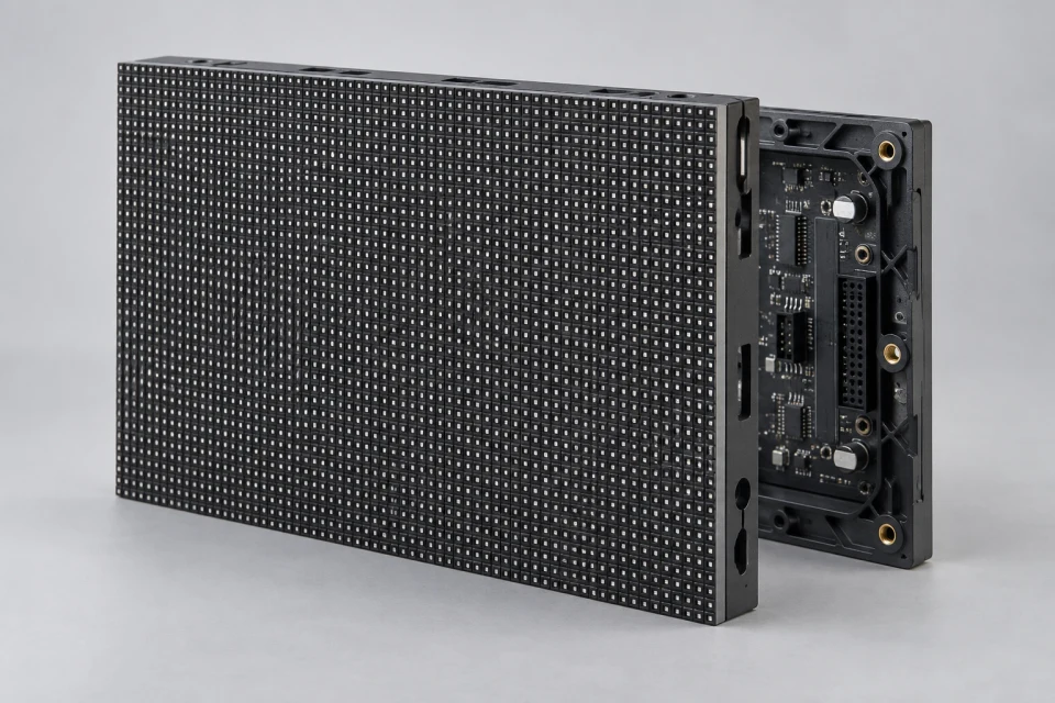
Specify module pitch, outline, fixing pattern and scan interface together so replacement panels fit both the cabinet and control chain.
View Component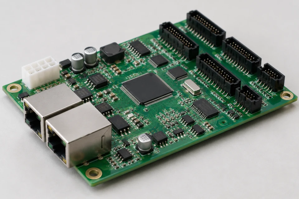
Distribute mapped image data at cabinet level with a receiver chosen for the sender ecosystem, pixel load and HUB interface.
View Component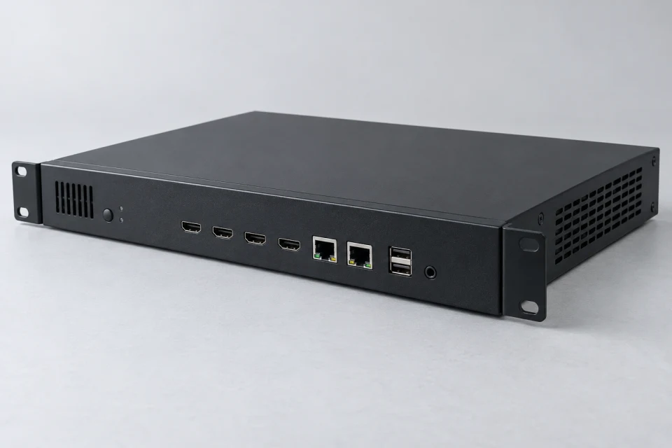
Send configured video output across the LED control network with port capacity and screen mapping reviewed before selection.
View Component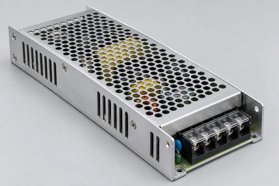
Match regulated DC output to the cabinet load, input supply, ventilation and planned maintenance access.
View Component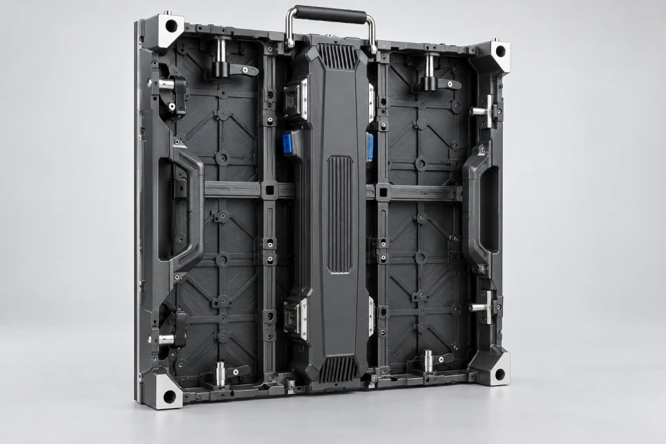
Keep module alignment and service access predictable with a cabinet chosen for the mounting grid, installation conditions and hardware layout.
View Component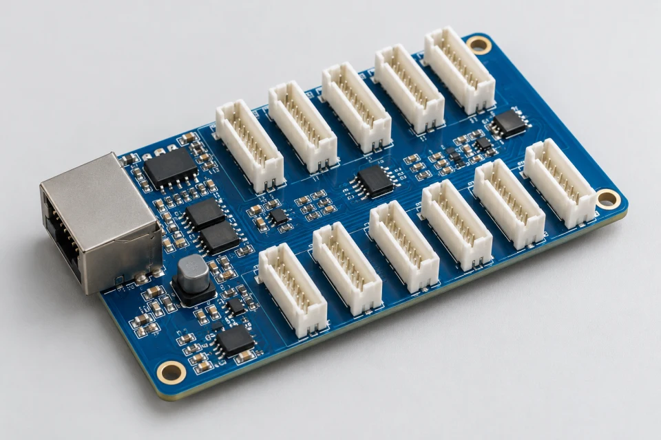
Route receiver output through the correct module pin map and connector orientation inside each LED cabinet.
View Component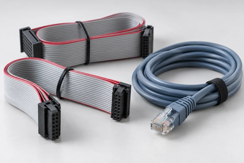
Select internal ribbon and inter-cabinet signal cables by connector pinout, route length, bend space and service exposure.
View Component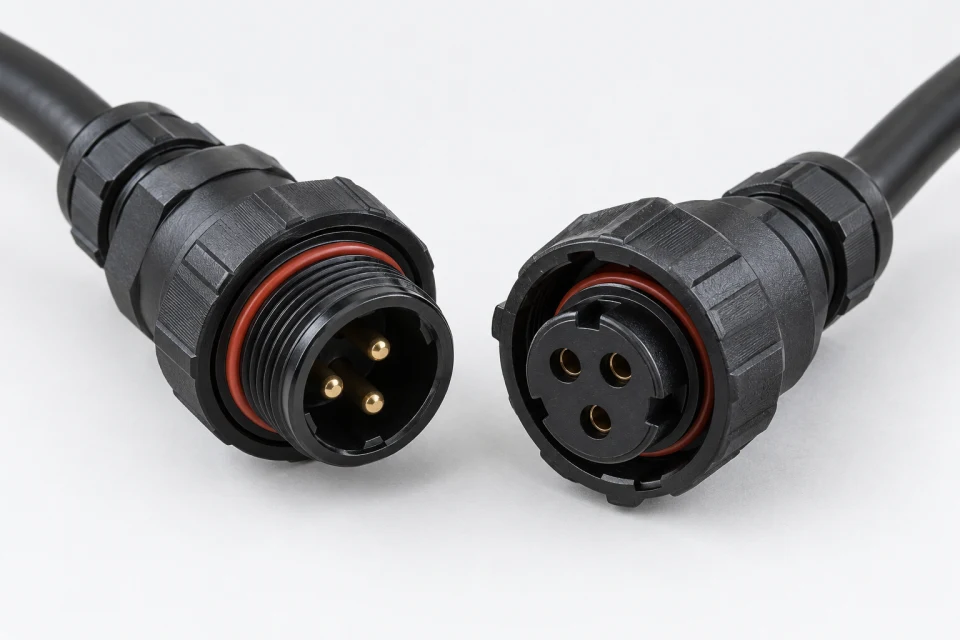
Maintain the planned environmental seal at power entry points with matched connector pairs and suitable cable terminations.
View Component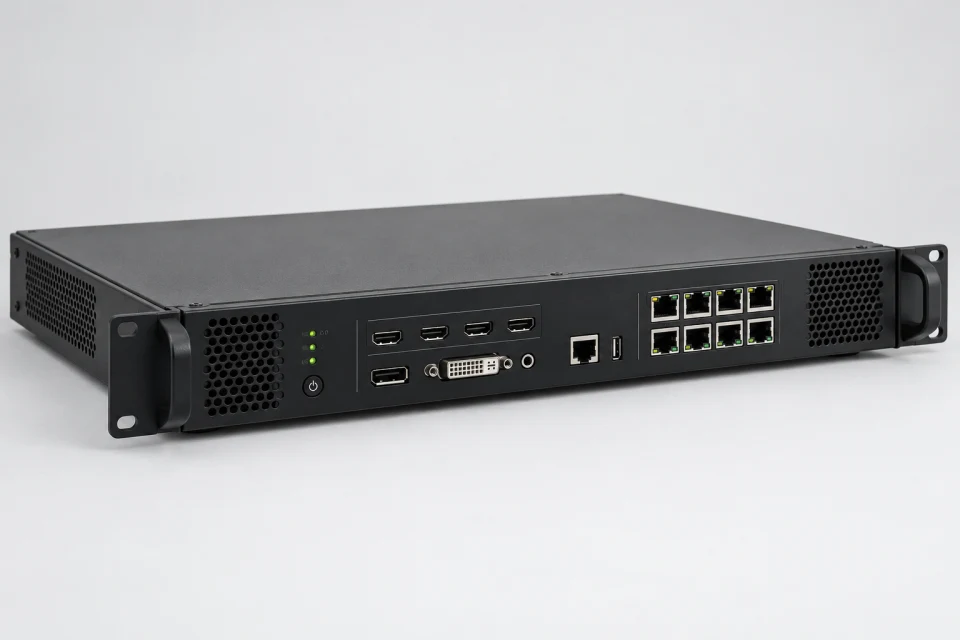
Coordinate sending, receiving, mapping and configuration hardware as a compatible display control package.
View ComponentInclude a photo of the existing part and its connection side, plus screen dimensions and quantity.